
MODRETRO Chromatic Disassembly

What you need

  1. MODRETRO Chromatic Disassembly, Battery Cover and Batteries: step 1, image 1 of 3 MODRETRO Chromatic Disassembly, Battery Cover and Batteries: step 1, image 2 of 3 MODRETRO Chromatic Disassembly, Battery Cover and Batteries: step 1, image 3 of 3
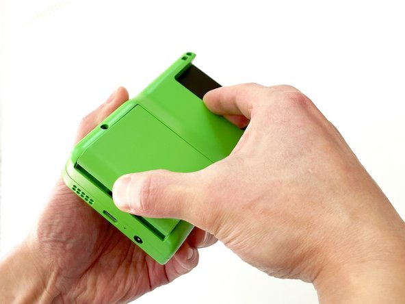
    • To remove the battery cover, push upward on the battery cover lock. The battery cover will pop open.

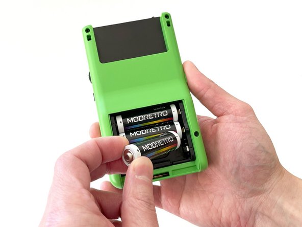
    • Lift the battery cover off and set aside.

    • Remove the batteries.

    • Always remove the batteries before working on your Chromatic!

  2. MODRETRO Chromatic Disassembly, Back Shell: step 2, image 1 of 3 MODRETRO Chromatic Disassembly, Back Shell: step 2, image 2 of 3 MODRETRO Chromatic Disassembly, Back Shell: step 2, image 3 of 3
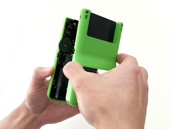
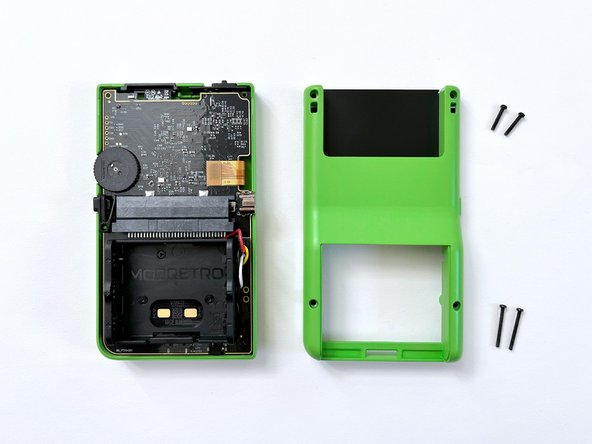
    • Remove the back shell screws (x4) using a Tri-wing Y1 Screwdriver.

    • The screws near the top are a different length than the screws near the bottom of the shell.

    • Remove the back shell by lifting away from the device.

  3. MODRETRO Chromatic Disassembly, Menu Button: step 3, image 1 of 3 MODRETRO Chromatic Disassembly, Menu Button: step 3, image 2 of 3 MODRETRO Chromatic Disassembly, Menu Button: step 3, image 3 of 3
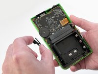
    • Remove the menu button by lifting it off the post. It will remove with little resistance.

  4. MODRETRO Chromatic Disassembly, Battery Tray: step 4, image 1 of 3 MODRETRO Chromatic Disassembly, Battery Tray: step 4, image 2 of 3 MODRETRO Chromatic Disassembly, Battery Tray: step 4, image 3 of 3
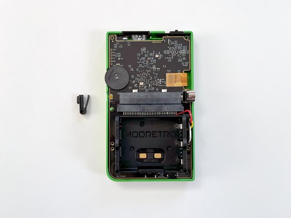
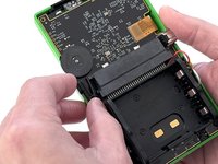
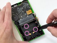
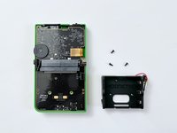
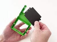
    • Remove the battery tray screws (x3) using a Tri-wing Y1 Screwdriver.

    • These are the only flathead screws in the device assembly.

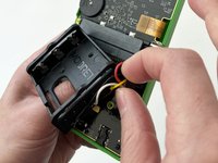
    • Remove the battery tray connector.

    • It is helpful to press lightly against the PCB with your off hand while working the connector loose.

  5. MODRETRO Chromatic Disassembly, PCB: step 5, image 1 of 3 MODRETRO Chromatic Disassembly, PCB: step 5, image 2 of 3 MODRETRO Chromatic Disassembly, PCB: step 5, image 3 of 3
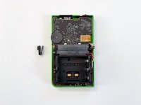
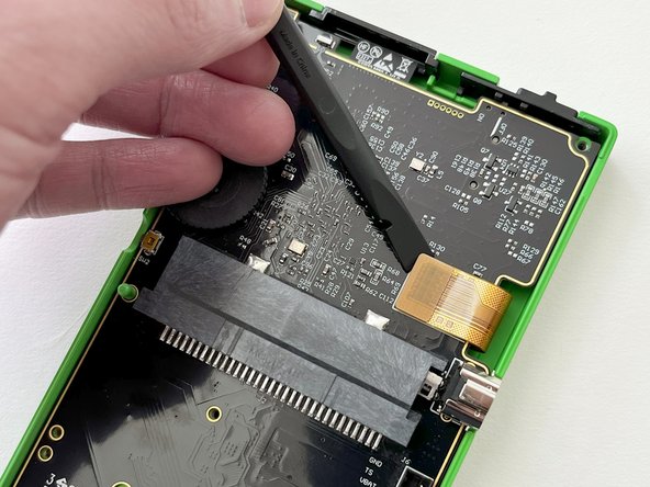
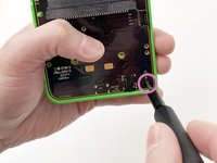
    • Remove the PCB screw (x1) using a Tri-wing Y1 Screwdriver.

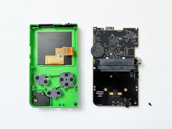
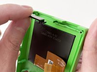
    • Carefully lift the LCD screen ribbon cable from the PCB.

    • Handle with care!

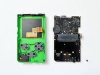
    • Carefully remove the PCB from the front shell.

    • Lifting at a slight angle will help clear the headphone jack on the bottom more easily. This is also important during re-assembly.

  6. MODRETRO Chromatic Disassembly, Speaker Module: step 6, image 1 of 3 MODRETRO Chromatic Disassembly, Speaker Module: step 6, image 2 of 3 MODRETRO Chromatic Disassembly, Speaker Module: step 6, image 3 of 3
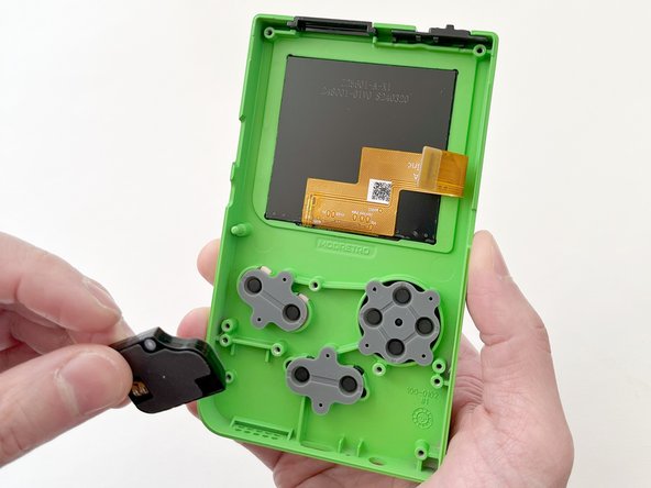
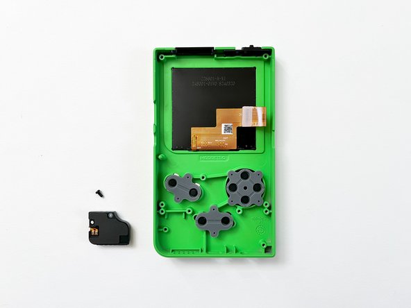
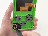
    • Remove the speaker module screw (x1) using a Tri-wing Y1 Screwdriver.

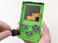
    • Carefully remove the speaker module from the front shell.

  7. MODRETRO Chromatic Disassembly, Buttons and Membranes: step 7, image 1 of 3 MODRETRO Chromatic Disassembly, Buttons and Membranes: step 7, image 2 of 3 MODRETRO Chromatic Disassembly, Buttons and Membranes: step 7, image 3 of 3
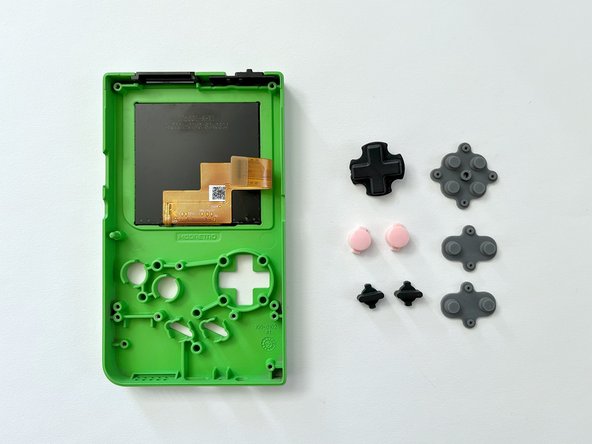
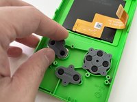
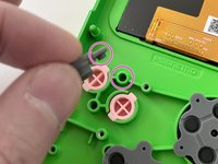
    • Remove the rubber button membranes (x3) from their pockets.

    • Remove the buttons and the D-pad from the shell with tweezers or by hand. If you flip the shell over, they will fall out freely.

    • The buttons will come out easily once the membranes are removed.

    • When re-attaching the rubber button membranes, be sure the positive features on the membranes seat securely into the pockets on the shell.

  8. MODRETRO Chromatic Disassembly, IR Window: step 8, image 1 of 3 MODRETRO Chromatic Disassembly, IR Window: step 8, image 2 of 3 MODRETRO Chromatic Disassembly, IR Window: step 8, image 3 of 3
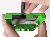
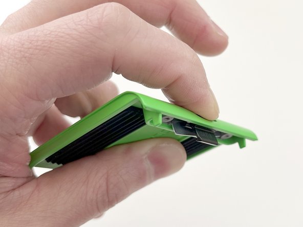
    • Carefully separate the IR window by gently wedging a plastic spudger between the IR window and the front shell.

    • Re-installing the IR window:

    • Note the side with the lip is inserted towards the front shell first.

    • Press in firmly until fully seated against the shell.

    • If the IR window fits loosely, the orientation is incorrect. The fit should be snug.

  9. MODRETRO Chromatic Disassembly, Power Switch: step 9, image 1 of 1
    • Remove the power switch by lifting away from the front shell. It will remove with little resistance.

    • When re-assembling the power switch, make sure it is inserted in the OFF position.

  10. MODRETRO Chromatic Disassembly, Cartridge Backer: step 10, image 1 of 3 MODRETRO Chromatic Disassembly, Cartridge Backer: step 10, image 2 of 3 MODRETRO Chromatic Disassembly, Cartridge Backer: step 10, image 3 of 3
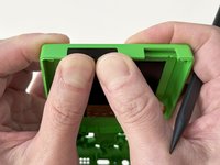
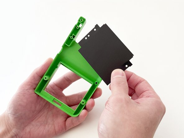
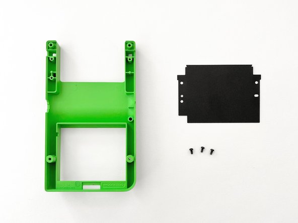
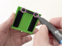
    • Remove the cartridge backer screws (x3) using a Tri-wing Y1 Screwdriver.

  11. MODRETRO Chromatic Disassembly, Battery Cover Disassembly: step 11, image 1 of 3 MODRETRO Chromatic Disassembly, Battery Cover Disassembly: step 11, image 2 of 3 MODRETRO Chromatic Disassembly, Battery Cover Disassembly: step 11, image 3 of 3
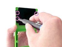
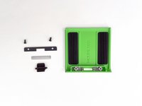
    • Remove the screws (x2) securing the latch cover using a Tri-wing Y1 Screwdriver.

    • Remove the door plate spring by fully depressing the battery cover lock. The spring should pop out.

    • Use a spudger if the spring does not fully dislodge.

    • Once the spring is removed, the battery cover lock can be removed without resistance through the underside of the battery cover.

Finish Line

2 other people completed this guide.

MODRETRO

Member since: 12/05/24

228 Reputation

1 Guide authored

0 Comments

Add Comment

View Statistics:

Past 24 Hours: 47

Past 7 Days: 320

Past 30 Days: 583

All Time: 583